Silicon-carbon anode materials are key for high-capacity lithium-ion batteries. Their development, therefore, depends on advanced preparation techniques. In this article, we will explore the three major preparation processes: mechanical ball milling, chemical vapor deposition (CVD), and spray pyrolysis. To begin, we will discuss these methods in terms of their principles, processes, equipment, evaluation, and applications. Furthermore, a detailed technical analysis and comparison will be provided for each technique.
Preparation of silicon-carbon anode materials by mechanical ball mill
The mechanical energy causes bulk silicon/carbon materials to repeatedly collide with grinding media, eventually forming nanoscale silicon-carbon composite particles.
Technological Process
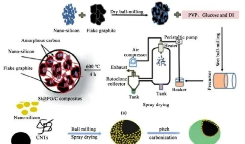
- Feeding and Mixing: We mix silicon powder, carbon materials (such as graphene and carbon nanotubes), and solvents to form a slurry.
- Wet Grinding: The slurry is fed into a sand mill for high-energy grinding (about 300 rpm, ball-to-material ratio of 10:1) to reduce the silicon particle size to nanoscale (<100 nm).
- Spray Drying: The slurry is atomized and quickly dehydrated in hot air to form micron-sized powder (particle size around 30-50 μm).
- Coating and Sintering: After coating with a carbon source, the material is sintered at high temperatures (600–1100°C) in an inert atmosphere to solidify the structure.
- Post-Treatment: This includes crushing, de-magnetization (magnetic field strength ≤ 5000 Gauss), sieving, and packaging.
Core Equipment
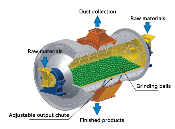
Ball Mill
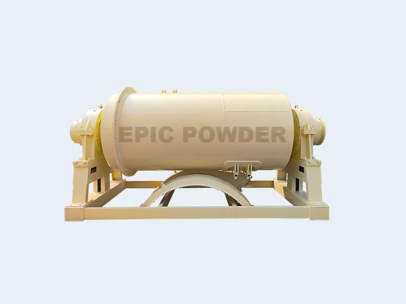
- Type: dry or wet ball mill.
- Key parameters: rotation speed, grinding media filling amount, inlet/outlet particle size (0.074 – 0.4 μm), production capacity.
- Auxiliary structure: step lining, steel ball grinding body, partition plate.
Mixing and drying equipment
- High-speed mixer (such as double propeller blade type): used for premixing silicon powder and graphite.
- Vacuum drying oven: temperature control 80–100℃, humidity ≤5% (to prevent agglomeration).
- Spray dryer: inlet/outlet air temperature is approximately 150-250℃ / 100-120℃ respectively.
Sintering and molding equipment
Full atmosphere protection electrode material calcining furnace, tablet press.
Evaluation
- Advantages:
The process is relatively simple and comes with low equipment investment costs. As a result, it suits large-scale production well. - Disadvantages:
However, the particle size distribution of silicon is difficult to control precisely. Additionally, there is a risk of introducing impurities and particle agglomeration. Moreover, the cycle stability is poor, with capacity potentially degrading to 1779 mAh/g after 200 cycles. Furthermore, over-grinding can damage the graphite crystal structure, increasing the likelihood of side reactions. - Applications:
The Silicon-carbon anode materials prepared by mechanical ball mill are mainly used in cost-sensitive, mid- to low-end power batteries or electric tool batteries.
Preparation of silicon-carbon anode materials by Chemical Vapor Deposition CVD
The gaseous silicon source/carbon source decomposes at high temperature. Deposited on the porous carbon skeleton to form a composite structure.
Technological Process
- Activation:
First, the porous carbon substrate (e.g., hard carbon) is heated to 800–1000°C under nitrogen protection. It is then held at this temperature for about 10 hours to expand the pores. - Silicon Deposition:
Next, silane (SiH₄) is introduced into a fluidized bed (400-650°C) or rotary furnace (800-1100°C) for pyrolysis (SiH₄ → Si + 2H₂↑). This process allows nano-silicon to deposit in the micropores of the carbon substrate (pore diameter < 2 nm). The holding time is around 5–10 hours. - Carbon Deposition:
Following this, acetylene (C₂H₂) is introduced for high-temperature pyrolysis (C₂H₂ → 2C + H₂↑). This forms a carbon layer that coats the silicon particles, buffering volume changes (temperature 800–1000°C). - Post-Treatment:
Finally, post-treatment includes mixing, electromagnetic impurity removal, sieving (target particle size ≤ 10 μm), and testing (magnetic material content ≤ 50 ppm).
Core Equipment
CVD Reaction System:
- Reactor Body:
The reactor uses a fluidized bed reactor with a smooth, sealed inner wall. This prevents material buildup. Alternatively, a dual-zone sliding tube furnace (e.g., rotary furnace) can be used. - Temperature Control System:
The system features molybdenum alloy heating elements. These elements withstand temperatures up to 1200°C. The temperature control precision is ±1°C. An N-type thermocouple monitors the temperature in real time.
Gas and Vacuum System:
- Six mass flow controllers (MFC) regulate gases like SiH₄ and C₂H₂. The precision is ±1%.
- A high-vacuum molecular pump system achieves a maximum vacuum level of 6.67×10⁻³ Pa. This prevents oxidation.
Safety and Exhaust Treatment:
- The system is explosion-proof. It includes a safety rupture disc and an external pressure detection tube (pressure tolerance ≥0.02 MPa).
- The exhaust is purified using an activated carbon adsorption box. We can equip it with a PE material filter and a combustion tower.
Evaluate
Advantages:
- Excellent Uniformity:
The gas-solid contact is sufficient, allowing silane to deposit in situ within the carbon pores. As a result, the coating layer is dense and evenly dispersed, which contributes to improved cycling performance. - High Efficiency:
The silane utilization rate can reach 95%, which is significantly higher than the 60% typical of traditional rotary kilns. This not only reduces raw material costs but also facilitates industrialization. - Strong Structural Control:
The process allows for precise control over the silicon content (10%-15%), particle size (20–100 nm), and pore distribution, offering excellent adaptability to specific requirements.
Disadvantages:
- High Equipment Sealing Requirements:
The equipment must have extremely tight seals to prevent the leakage and explosion of toxic, flammable silane, which poses a significant challenge. - Strict Temperature Control:
Temperature control must be precise. The exothermic nature of the reaction requires segmented temperature control, while cooling gases are essential to avoid localized overheating. - Limited Equipment Capacity:
Currently, mainstream equipment has a capacity of about 100 kg . To scale up to ton-level capacities, CFD simulations are needed to optimize the flow field.
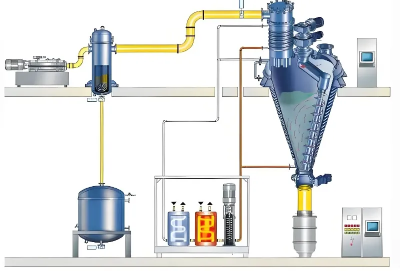
Spray Pyrolysis
The precursor solution is atomized. Then, it undergoes thermal pyrolysis and sintering in a high-temperature furnace. This process forms silicon-carbon composite materials.
Core Equipment
Evaluate
- Advantages:
The process is continuous, which ensures relatively good batch-to-batch stability. Additionally, it is easy to incorporate materials such as carbon nanotubes or graphene, which help improve conductivity. - Disadvantages:
However, the cracking temperature is relatively low (≤500°C), which results in insufficient stability of the carbon layer structure. - Applications:
Currently, the process is in the development stage. Its target application is fast-charging batteries, leveraging its low expansion characteristics. - Automation Control System:
The system is equipped with a touch-screen PLC that integrates control of temperature, flow rate, and liquid level for enhanced operational efficiency. - Exhaust Treatment:
We treat exhaust gases through a TO furnace (thermal oxidation combustion), followed by an activated carbon adsorption box to ensure thorough purification. - Powder Collection System:
The powder is collected through multi-stage filtration, such as a three-stage sieve. The target particle size is 1–3 μm, ensuring high-quality collection. - Pulse Dust Collector:
The pulse dust collector achieves a purification efficiency of ≥99% and includes an automatic dust collection hopper for easy handling. - Micro-Mist Generator:
We use an ultrasonic atomizer to generate liquid droplets in the range of 1–10 μm, providing precise mist formation. - Gas-Liquid Co-Flow Valve:
The gas-liquid co-flow valve features a variable diameter pipe design, ensuring a gas-liquid flow ratio of about 100:1 for optimal performance. - Tube Furnace for Cracking:
The tube furnace has dual temperature zones, with temperatures ranging from 300–500°C. Moreover, we can introduce reductive gases to further optimize the process.